The PicoBlaze is one of the simplest processor to program in assembly language. Thanks to its RISC (
Reduced Instruction Set Computing) architecture. A RISC processor only have a few instructions (about 20 of them), compared to a CISC (
Complex Instruction Set Computing) processor. Having less instructions means that they can be packed at a higher density (because of the
opcode length), thus requiring a smaller program memory. Moreover, it's easier to learn!
The PicoBlaze has been created by Ken Chapman from Xilinx and you can find an excellent and comprehensive documentation on the processor from Xilinx's User Guide 129 (UG129). I suggest you get it now.
Instructions groups
Before doing some programming, let's talk a little bit about the purposes of the PicoBlaze instructions and group them by category.
Arithmetic
These instructions are used to make simple calculations. It is possible to use them in a loop to perform more complex operation like multiplication, division, square root, power... The carry (added C) variant is used to make calculations on numbers larger than a byte (255). These operations modify the processor flags, more on that in a moment.
Logic
These logic instructions are used to perform
bitwise operations on two bytes. They are often used to set, clear or toggle bits. This is done with a technique called
masking; I'll give you some example in a next article on microprocessors programming.
Bit manipulation
To perform operation at a bit level, it is often useful to
shift (or rotate) the bits in a byte. Shifting to the left or right can be useful for multiplication or division by a multiple of 2 (see binary number mathematical property). Often, when doing IO or mathematical operations, the bits you want to manipulate are located at the wrong position in the byte; you can solve the problem with these instructions. There is a subtle difference between shifting and rotating. When rotating, the bit that is pushed out of the byte (either 1 or 0) is fed back at the empty position. While shifting, that pushed bit is lost and the empty position is replaced either by a 1 or 0, depending if you use S?1 or S?0, respectively.
- RL / SL0 / SL1
- RR / SR0 / SR1
Testing
These two operation (especially COMP) are essential to create conditionals. But before, you need to understand the
processor flags. In the PicoBlaze, there is 2 status flag bits, ZERO (Z) and CARRY (C). The ZERO flag bit is set when the result of the last operation is zero. The CARRY flag bit is used to indicate various conditions, often used to signal a overflow/underflow condition while adding or subtracting. Back to our instructions... COMPare is used like a dummy SUB operation. The two bytes are subtracted (result not written back): if the Z flag is set, the numbers were equal; if the C flag is set, we know which number was greater than the other. The TEST instruction is a bit less used. It works like a dummy AND, the two numbers are "ANDed" together. If the result is zero, the Z flag is set. If there is a odd number of 1 bit in the resulting byte, the C flag is set (this is used to
check the parity).
Memory manipulation
The LOAD instruction is used to move a register/constant value in another register. The FETCH and STORE instruction are used respectively to get data from scratchpad RAM into a register and put a register value into the scratchpad RAM. These operations are useful because you can reserve RAM or register address for a certain purpose and often, you need to move data to/from them.
Program redirection
The last piece of the puzzle, program
flow control. The CALL/RETurn statements are used to describe functions that are called multiple times during the program lifetime (examples: doing a complex mathematical operation or getting a scaled value from a sensor). The inner working if these two instruction is simple: when CALL is executed, the address of the next instruction is
pushed on a special memory space called
the stack. The program flow then branch to the function and execute it until the RET instruction is encountered; the return address is then
popped from the stack into the program counter (remember? the register that hold the value of the address of the current instruction).
The stack allow multiple CALL to be nested. The JUMP instruction is often used with conditionals, where some instructions can be skipped depending of the current Z and C flags value.
Hello, PicoBlaze!
Enough theory, let's run the IDE and write some code (very small executable file,
download it here). If you are using Linux, it works well under
Wine. More info is available on
Mediatronix's website, the maker of the IDE.
Our first PicoBlaze program will be simple and not really useful. Though it's great for learning purpose. We are going to write the number 0 to 63 in the 6-bit scratchpad RAM, backward! The picture below is the simulation result of the program (you can see the hexadecimal numbers in the ScratchPad0 debug area):
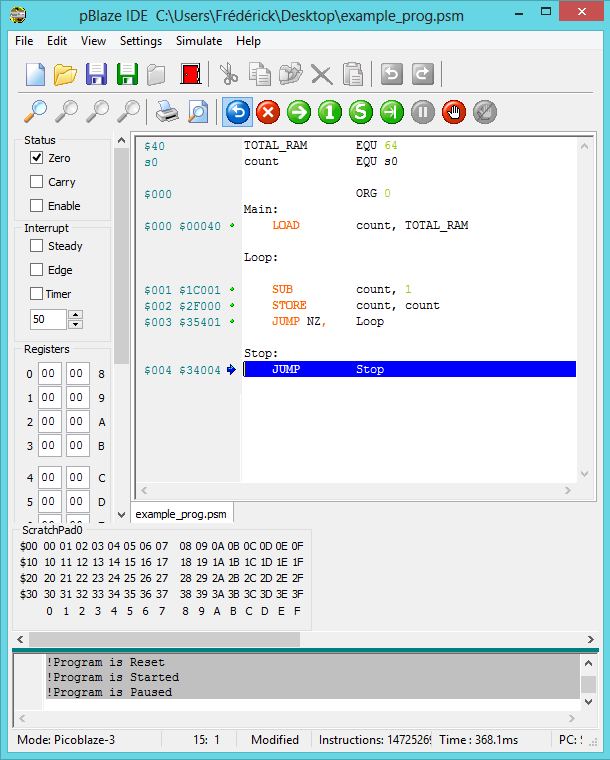
Before using the program, choose Picoblaze 3 in Settings (shortcut Ctrl+3). This is important! If you don't select this option, my sample code will not compile. Take a look in the bottom left corner of the window above, you should see Mode: Picoblaze-3.
The pBlazIDE is used to write the PicoBlaze program and simulate it in a convenient environment. When you open the IDE, you can either create a new project (Ctrl+N) and write the above program or just
download mine and open it (Ctrl+O). When it's done, click the Assemble & Simulate (F12) button. The simulation mode is really cool because you can view the flags status, content of the registers, scratchpad memory, IO, etc... When you are in simulation, run (F9) the program, then pause it with the red button at the right (the one at the left is used to reset the simulation). You should be able to see the content of the ScratchPad0 area filled up.
Let's review the code line by line:
- The EQU keyword is used to assign a name to a register/constant value (this is optional). The TOTAL_RAM label will be used to represent the decimal value 64 (the total number of RAM register address).
- The register s0 will be used to store the count from 64 to 0. Let's name it that way.
- The ORG keyword is used to select the starting address of the following instructions. We put our program at the beginning of the program memory (address 0).
- The keywords followed by a colon are called label. It is conventional to name the address of our first instruction (Main:).
- The LOAD instruction is used to move a value into a register. In this case, we move 64 in the s0 register. Instead of using the EQU directive, we could have explicitly written LOAD s0, 64.
- The Loop: label is used to reference the address of the SUB and following instructions that we will repeat 64 times in a loop.
- Each time we go through the loop, we subtract 1 from the count register (s0). When the result of the subtraction will be 0, the Z flag will be set.
- We want to fill the RAM so we store the count value at the count address with the STORE instruction. The first time 63 (3F) will be written at address 63 (3F). At the end, 0 will be written at address 0. This is why it counts backward :)
- While the Z flag is not set, the JUMP NZ, will go back to the Loop label address. When the SUB instruction result will update the Z flag, this JUMP instruction won't be executed. Read the instruction like it were JUMP (if) NotZero.
- The two following lines are used to create an infinite loop that JUMP on itself. In a real life situation it is important to stop the execution of the program in a certain way because it will continue to execute the bits in memory in a unpredictable way.
Please note that I changed the color setting of the IDE syntax. In the picture above, there is 5 orange instructions (LOAD, SUB, STORE, JUMP, JUMP). These instructions are what is written in the program memory. Everything else is directives and labels. Once assembled with the pBlazASM.exe utility (you can find it on the website mentioned above), the binary that goes into the program memory is reduced to (in hexadecimal):
00040
1C001
2F000
35401
34004
Conclusion
I hope that you found this article interesting and you learned new stuff. I would like that you guys try to create a simple program or modify mine (using information in UG129) and play around with the IDE. Send me your experiments on my email address: fred_blais5(at)hotmail.com and I would be glad to showcase some of your programs in a next article. Also, don't hesitate to write programming ideas in the comment section, I'm all ears!


