24 Mar 2013

Milestones in digital electronics evolution

Ask someone about what electronics is, the answer will probably be related to all the modern devices we're using everyday : mp3 players, televisions, computers, cell phones... All of these are made of many integrated circuits containing millions of transistors (sized in nanometer). In numeric circuits, you always need a switching device that can be used to create logic gates and registers. However, these switches have not always been as small as they are today. Here are some milestones in the advances of modern electronics.

The mechanical relay (1835)

The relay is one of the oldest device used to make computers (primitive ones) and is still used a lot nowadays in all sort of different applications. The basic relay consist of a coil, spring, armature and contacts. When the coil is energized the armature close the normally open contact, otherwise the spring maintains the normally closed contact.


Computer with limited programming capabilities could be made using relays, like the Z1 in germany around 1938. It is considered as the first freely programmable computer, but it's operation was unreliable.


The vacuum tube (1907)

The vacuum tube is a great improvement over the mechanical relay because it contains no moving parts, that means it's a lot more reliable. Like the transistor, the vacuum tube can be used as an amplification device or as a switch. Hi-fidelity audio equipment still use vacuum tubes, for the clarity of the sound it provides. However, it is no more used as a switching device.


The first computers using vacuum tubes appeared around 1945 : the Colossus and the ENIAC. They were quite power hungry and heavy machines. The ENIAC contained around 17500 vacuum tubes as well as 1500 relays.


The transistor (1954)

The transistor is the device of choice to create digital electronics circuit and has evolved considerably since it's beginnings. The biggest advantages of the transistor over the vacuum tube is it's small size and small power consumption. That marks the debut of lightweight and portable electronics. In the picture below, you can see a replica of the first bipolar junction germanium transistor.


With the invent of the transistor, computers got a lot smaller and were ready to be manufactured for the commercial market. The IBM 608 is one of these fully transistorised computers. Below, a picture of Harwell CADET computer.


The integrated circuit (1962)

Transistors really began to get small when packaged into chips. That way, a lot of transistors could be packed on the same "die". I bet you have ever heard about Moore's law, stating in 1965 that the transistors count in integrated circuits will double every year for at least ten years. Here is a picture (a little bit outdated) representing the advances in the number of transistor in IC.

As you can see, the first generation of integrated circuits were used to make logic gates. Lots of things could be done with simple TTL gates, take a look at this circuit schematic of an arcade machine Pong game made by Atari in 1974.


 Generations of computers

I found an interesting article about computer generations here's the summary (mechanical relay computers not included) :
  1. First Generation (1940-1956) Vacuum Tubes
  2. Second Generation (1956-1963) Transistors
  3. Third Generation (1964-1971) Integrated Circuits
  4. Fourth Generation (1971-Present) Microprocessors
I bet you learned something new about computers... That's all for today folks!

23 Mar 2013

Serial and parallel I/O : shift registers

Sequential logic

When I discussed about digital logic, I mostly focused on combinational logic (decoders, adders...) but there is another really important type of digital circuits : sequential logic circuits. Sequential logic circuits are circuits that the outputs not only depend on the inputs, but also of the order in time that these inputs are read. Some new terms are introduced in this circuit type.

First of all, the concept of the memory bit : if the sequential circuit is time dependent, it means that there is some way to memorize the internal state of the circuit at a given time period. This is done with bistable circuits called latches or flip-flop (more on this in another article) that can be used as storage elements. If we combine more than one of these memory bits together, we can create registers.

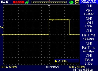
Most of the time, sequential circuits work with a clock signal. A clock signal is a stream of square wave pulses that is used to synchronize the circuits. With the clock signal, data can be serialized on a single wire. This is the basis of high-speed computer buses. Here is examples waveform of a I2C bus transaction. The SDA signal is serial data and the SCL signal means serial clock and is square wave signal. The data being transferred is something like 011011001...


Shift registers

An interesting sequential logic device is the shift register. The shift register is a clocked device and can work in many modes. In the picture below, the blue cubes are memory bits and red arrows represent data being shifted right each clock cycle. Data can be shifted at the rising or falling edge of the clock pulses (depending on the IC). As you can see, inputs can be serial or parallel and outputs can also be serial or parallel. We're going to see two example of chips using a shift register.


Serial to parallel with the 74HC595 IC

The 74HC595 chip is often called an outputs expander. This is due to the fact that a µC (microcontroller) or other devices that can talk serially to this chip have the possibility to add a few output lines to their I/O. Has you may have already guessed, this IC is a serial input, parallel output shift register. With a single 595, you can add 8 output lines with as few as 3 wires. What's interesting is that you can daisy chain multiple 595 to add 16, 24, 32 and more outputs with only 3 control wires.

To be able to understand the inner working of that chip, I used it's datasheet. Below are some information that I found concerning the pin-out of the chip and the pins functionality.


The interesting pins are the 8 parallel outputs (Q0-Q7) and the 3 control pins : STCP (latch), SHCP (clock), DS (serial input). The OE pin is the output enable and must be tied to the ground to activate the outputs. MR is the master reset, tie it to Vcc (positive supply voltage) to get the chip out of the reset state.


In the table below, you can easily see what is going to happen with a given set of inputs. To make that short, a rising edge on the clock pin (SHCP) will store the serial input bit (DS) in the least significant bit (Q0S) of the shift register. All the previous bits in the shift register will move one bit toward the most significant bit (Q7S) one clock at a time. When the latch input is pulsed (STCP) the actual content of the shift register will be saved in the storage register. The storage register is directly tied to the parallel output (Q0-Q7). Remember that you must activate OE to make the outputs visible.


I wrote a driver in SPIN (the language used by my favorite µC, the P8X32A) to drive the 74HC595. I hope that in a couple of article I can write some tutorials about microcontroller programming. If you are a bit familiar with programming languages and algorithm, you should easily understand the code below.


You can see the result of the code on a LED bar-graph. On the first picture, $FF (1111_1111) was sent to the 595. On the second one, $55 was sent (0101_0101), can you see it? Please note that the 595 only has 8 output, so I only use 8 of the ten available LED on the bar-graph. Besides, I burned these two LEDs by doing some experiments on the bar-graph without current limiting resistors, duh!


Parallel to serial with the 74HC165 IC

The 165 IC is a parallel input, serial output shift register. Almost everyone has already used a device containing a 8 bit parallel to serial static shift register, if you ever played with an old Nintendo Entertainment System :)


In fact, this is the kind of chip used to store the 8 NES controller buttons (start, select, A, B, up, down, left, right) state and send it serially to the console. This operation is performed several times in a second. This can be seen as the inverse operation of the 595, as an input pins expander.

The working principle is quite simple : when PL (parallel load) is asserted, data from (D0-D7) are loaded in the shift register. After that, the bits are sent serially to Q7 (serial output from last stage) on each rising CP pin (clock) pulses.


I think that this IC is a little less interesting to demonstrate, as the data end up in the microcontroller and cannot really be seen... Though, it could be interesting to make some kind of gamepad with this IC as a demonstration. Moreover, the development board that I use has 2 NES gamepad port on it. Here is the source code for dealing with two gamepads (thanks to XGameStation, the developers of the board) :


Still here? :)

There was a lot of new information in this post, I did my best to make it the clearer and easier to understand as possible. For the lines of code shown, as I said, I will blog about programming later but there is a lot of interesting things to see before delving into that. Do not hesitate to write suggestions in the comment box!

19 Mar 2013

The 555 timer IC

In my previous post on diodes, we saw how to light up an LED. This was exciting, for the ones who made their first step in electronics! What would be even more exciting is blinking that LED at a chosen rate. With what we're going to see today, you'll be able to do that easily.

The venerable 555 timer

The 555 has been introduced in 1972, and is still used a lot nowadays, with an estimated production of 1 billion device every year. There is multiple ways for generating pulses of different duration, but learning how to do it with the 555 timer is essential, and no programming is required. By setting a capacitor and resistors values, you can choose the timing you need. The 555 timer can be used in three different modes. Here is a picture of a breadboard with a 555 chip in monostable mode (notice the push-button used for triggering and only one resistor used on the chip pins).


Monostable (one-shot mode)

In this mode, the 555 is configured to generate a single pulse when a signal is sent to the trigger (TRIG) pin of the device. As you can see, there is a bar over the "Trigger" net name. This means that the pin works with inverse logic signals. You have to connect it to the Vcc supply through a pull-up resistor (let's say 10k) and bring it down to the ground net to trigger the one-shot pulse. This is useful if you want to turn on a device only for a certain duration e.g. motors, LEDs, lasers, relays, transistors...


Here is a screenshot with my oscilloscope of the one-shot pulse in the monostable mode, triggered with a push button. I used a 10µF aluminum capacitor with a 100k resistor. The width of the pulse should be 1.1 seconds, but capacitors values varies a lot. In this case, a smaller resistor value could have been used to reduce the duration of the signal.


Monostable Mode R:Ohms
C:uF (microfarads)


Bistable (latching mode)

In this mode, the 555 is not used as a timer, it is more like a memory bit that can be set or reset. This is similar to a SR latch that is found in digital circuits. When set, the OUT pin of the 555 will go high and will stay at this level until the reset pin receive a signal. This mode is used when you want to permanently turn on a device with the set (TRIG pin) button, until the reset (RESET pin) button is pressed. Electricians will recognize this behavior from a start-stop relay wiring. 


Astable (pulses stream mode)

In this mode, the 555 will output rectangular waves that you can configure the on and off time with two resistors and one capacitor. This is the mode that you use to blink LEDs. The outputted frequency will depend on the high and low time of the repetitive waves. Something interesting to note is that if you change the value on the capacitor without changing the resistors value, the duty cycle will stay the same. So set your duty cycle first with the resistors and adjust the frequency with the capacitor.


Here is a screenshot with my oscilloscope of the stream of pulses in the astable mode. I used a 10µF aluminum capacitor with 10k/100k resistors. Here again the capacitor tolerance has an effect on the timing.


Astable Mode R1:Ohms
R2:Ohms
C:uF (microfarads)