The seven-segment display
It is likely that you've already seen a 7-segment in a numeric watch or clock. This device contain 7 LEDs (hence 7-segment) enclosed in a small plastic case. It is generally used to display decimal digits from 0 to 9 (and display hexadecimal digit A to F). There are also some version of the 7-segment that contain a decimal point LED.
Being a 7-bit device, the 7-segment can display 128 (2^7) different "symbols". Take a look at this chart that shows all the possible combinations :
Driving the display with a decoder
The fact is that we don't really need all these combinations. We can then cut down 3 bits and have 16 (2^4) possible patterns, enough to hold the numbers 0 to 9. This is the goal of the 4 bit in, 7 bin out decoder as shown below :
In the picture, you can read the term BCD (Binary Coded Decimal) that means a 4-bit code representing the decimal digit coded in binary (as the name imply). The BCD to seven-segment decoder can be implemented with simple logic gates (see picture below).
The CD4511 to the rescue
I already implemented a 7-segment display decoder with 74 series logic gates when I was in college and it was quite a challenge to get it working (without doing any wiring mistakes)! Integrated circuits like the CD4511 does the same thing, but in a tiny DIP package. Here is the basic schematic of a circuit using the decoder :
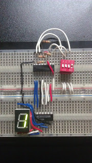
The "Lamp test" pin is used to light all the LED on the seven-segment to check if it's working properly. The "Blanking" pin does the opposite, it blanks the display. These two pins can be tied to the positive power rail as they are rarely used. The "Latch enable" pin, when pulled down to the ground, refresh the display with the current input (A0 to A3). The wiring is pretty straightforward, below is two pictures of what it looks like on a breadboard :
The CD4511 in action
There is multiple way to drive a decoder. It can be with simple DIP switches, or driven by a microcontroller. In the second video, I use 4 outputs of the Parallax Propeller to drive the chip. In the program I made, the delay between the counts is randomized between 150-1000 ms so the result is a bit more interesting...


Thnx man....very helpful
ReplyDeleteThanks. I've been busy this summer but I will be back with new stuff as soon as I can :)
ReplyDelete