The venerable 555 timer
The 555 has been introduced in 1972, and is still used a lot nowadays, with an estimated production of 1 billion device every year. There is multiple ways for generating pulses of different duration, but learning how to do it with the 555 timer is essential, and no programming is required. By setting a capacitor and resistors values, you can choose the timing you need. The 555 timer can be used in three different modes. Here is a picture of a breadboard with a 555 chip in monostable mode (notice the push-button used for triggering and only one resistor used on the chip pins).
Monostable (one-shot mode)
In this mode, the 555 is configured to generate a single pulse when a signal is sent to the trigger (TRIG) pin of the device. As you can see, there is a bar over the "Trigger" net name. This means that the pin works with inverse logic signals. You have to connect it to the Vcc supply through a pull-up resistor (let's say 10k) and bring it down to the ground net to trigger the one-shot pulse. This is useful if you want to turn on a device only for a certain duration e.g. motors, LEDs, lasers, relays, transistors...
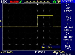
Here is a screenshot with my oscilloscope of the one-shot pulse in the monostable mode, triggered with a push button. I used a 10µF aluminum capacitor with a 100k resistor. The width of the pulse should be 1.1 seconds, but capacitors values varies a lot. In this case, a smaller resistor value could have been used to reduce the duration of the signal.
Bistable (latching mode)
In this mode, the 555 is not used as a timer, it is more like a memory bit that can be set or reset. This is similar to a SR latch that is found in digital circuits. When set, the OUT pin of the 555 will go high and will stay at this level until the reset pin receive a signal. This mode is used when you want to permanently turn on a device with the set (TRIG pin) button, until the reset (RESET pin) button is pressed. Electricians will recognize this behavior from a start-stop relay wiring.
Astable (pulses stream mode)
In this mode, the 555 will output rectangular waves that you can configure the on and off time with two resistors and one capacitor. This is the mode that you use to blink LEDs. The outputted frequency will depend on the high and low time of the repetitive waves. Something interesting to note is that if you change the value on the capacitor without changing the resistors value, the duty cycle will stay the same. So set your duty cycle first with the resistors and adjust the frequency with the capacitor.
Here is a screenshot with my oscilloscope of the stream of pulses in the astable mode. I used a 10µF aluminum capacitor with 10k/100k resistors. Here again the capacitor tolerance has an effect on the timing.


No comments:
Post a Comment